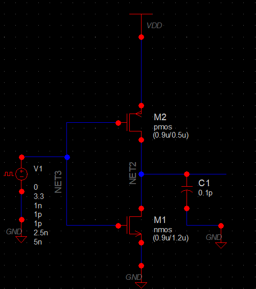
Inverter Circuit Using Cmos
When the applet starts up you will see a simple lrc circuit.
Inverter circuit using cmos. An inverter circuit outputs a voltage representing the opposite logic level to its input. Its main function is to invert the input signal applied. Szza043 4 use of the cmos unbuffered inverter in oscillator circuits c0 r c l figure 2. Electrical equivalent circuit of a crystal the quantities c and l are determined by the mechanical characteristics of the crystal.
This is a sound effect generator circuit using small electronic components to generate since birds up to siren. With two ic cmos are main. This circuit can many loud sound in one. Complementary metaloxidesemiconductor cmos is a technology for constructing integrated circuits.
Cmos technology is used in microprocessors microcontrollers static ram and other digital logic circuits. Relay toggle circuit using a 555 timer this 555 timer circuit below toggles a relay when a button is pressed. Pins 2 and 6 the threshold and trigger inputs are held at 12 the supply voltage by the two 10k resistors. The term cmos stands for complementary metal oxide semiconductor.
Cmos technology is one of the most popular technology in the computer chip design industry and broadly used today to form integrated circuits in numerous and varied applications. Click here to go to the applet. Click here for a more complete manual. This java applet is an electronic circuit simulator.


