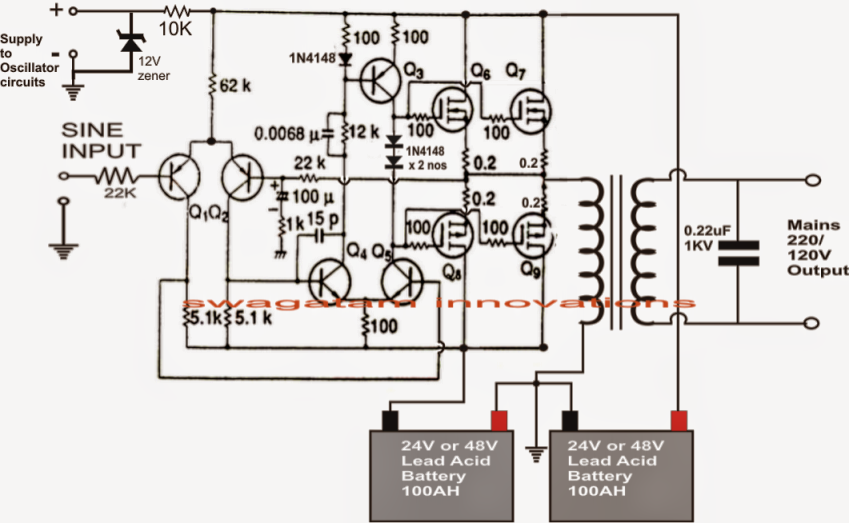
Arduino Pure Sine Wave Inverter Circuit
These modified inverters produce a square wave and these are not used to power delicate electronic equipments.
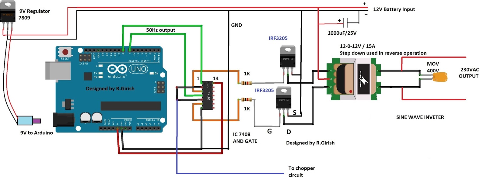
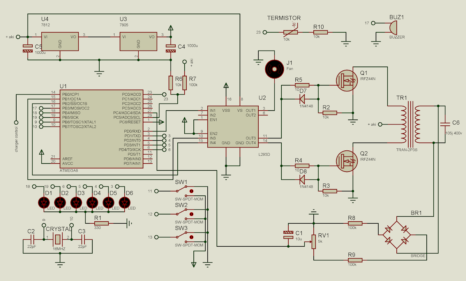
Arduino pure sine wave inverter circuit. I mean that if the dc input voltage decrease or increase this will lead to decrease or increase the rms output voltage of the inverter and also if the output load decrease or increase this will lead to increase or decrease the rms output voltage of the inverter because the look up table only at one case. Here is a simple but powerful stable and efficient schematic diagram for a 500w modified sine wave inverter circuit. Originally i used a 555 timer and a cd4017 decade counter to produce the modified sine wave but then i thought a simple pic micro controller with its internal clock would produce a stable 50hz60hz frequency without the need. All the sgca 3524 circuits presented on the net are missing a vital componentcircuit.
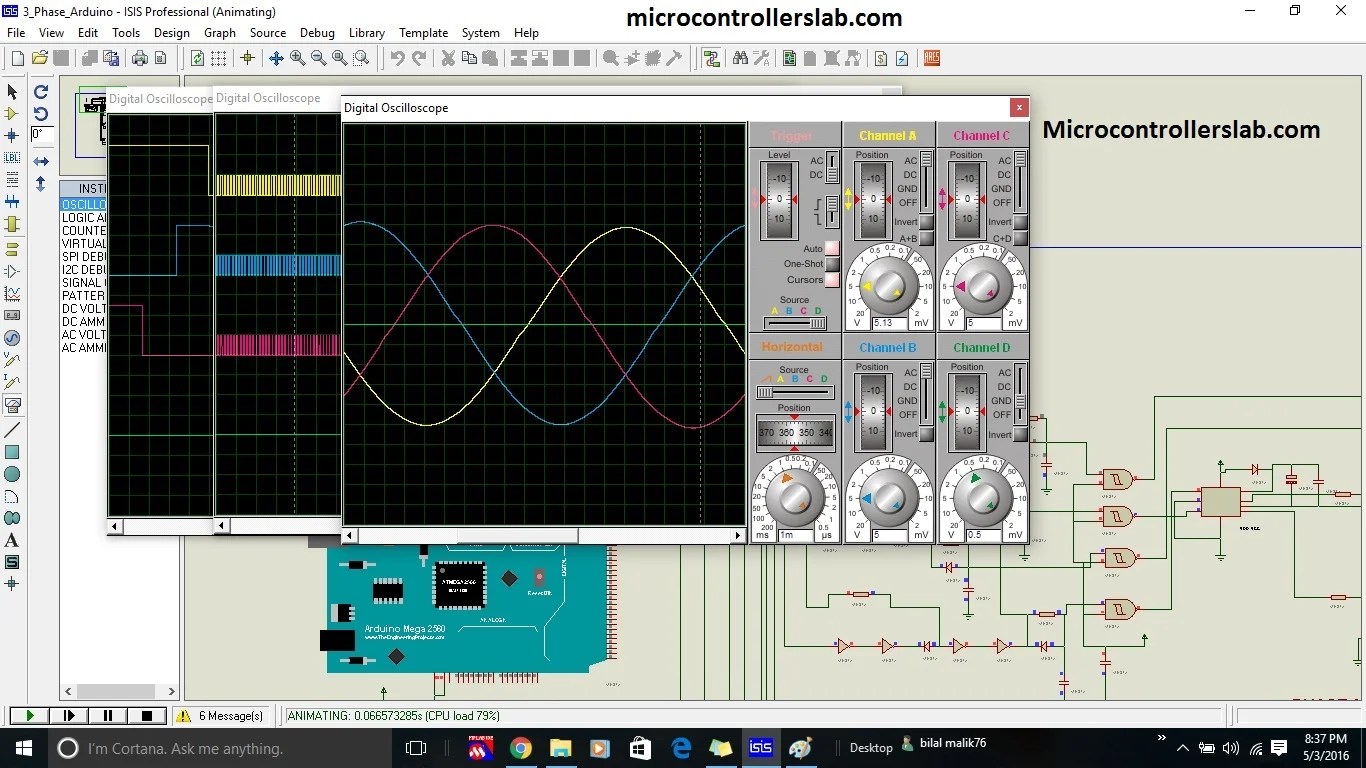
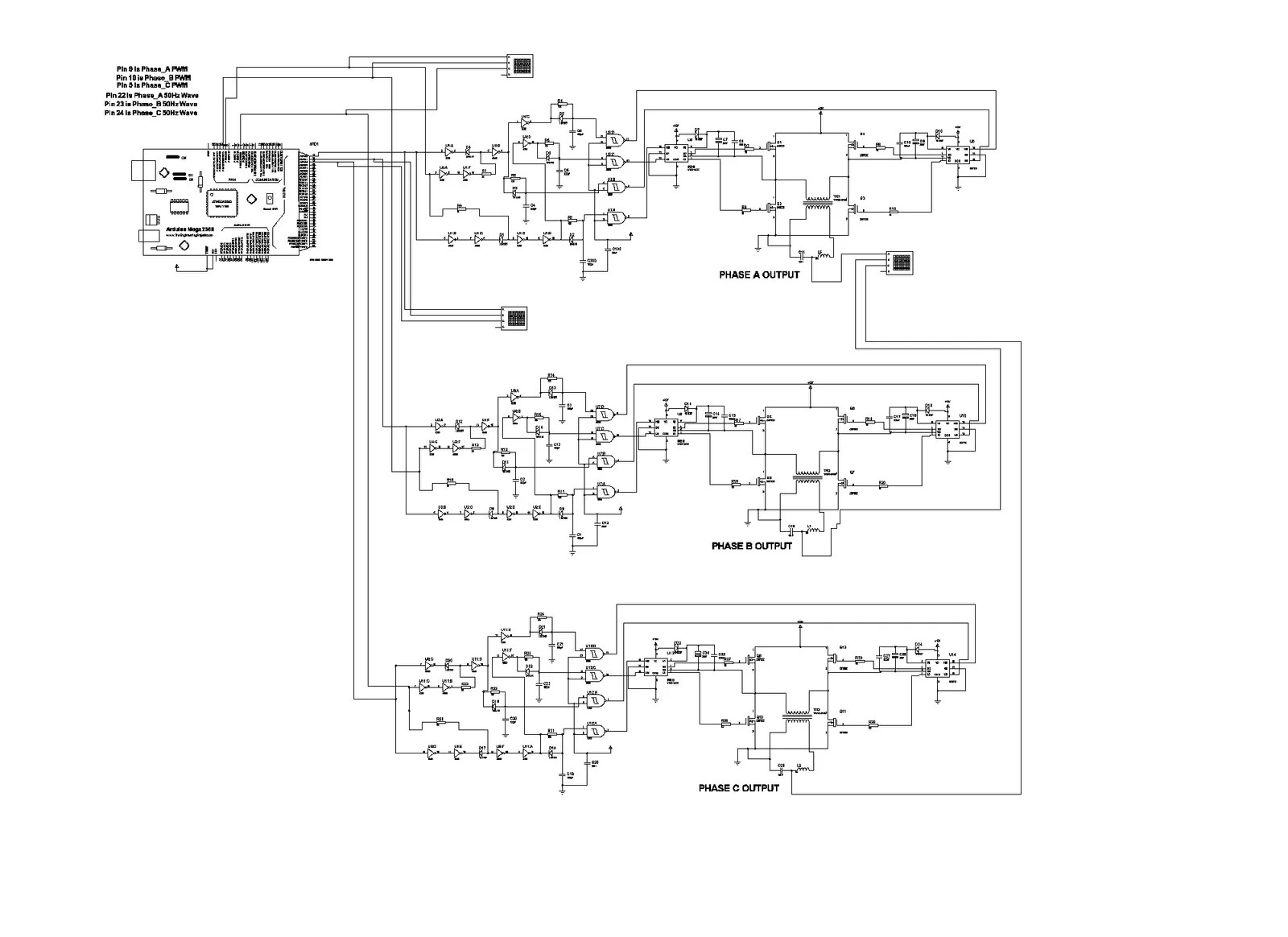
That is to say the sg3524 has been wire to produce a fixed pulse width which does not produce a sine wave behavior at the transformer. Stack exchange network consists of 175 qa communities including stack overflow the largest most trusted online community for developers to learn share their knowledge and build their careers. The post discuses the how to make a 3 phase inverter circuit which can be used in conjunction with any ordinary single phase square wave inverter circuit. Home power inverter is to provide uninterrupted power to run household electric devices.
These inverters for home are available in different voltage and load capacities. Here is a very simple pure sinewave inverter based on the microntoller pic 16f628a dont freak out no it is not difficult to use microntollers actually it could not be any easier than this. 100 watt inverter circuit diagram parts list design tips. Inverters are devices that convert dc input supply to ac alternating current.
They are also called power inverters.


