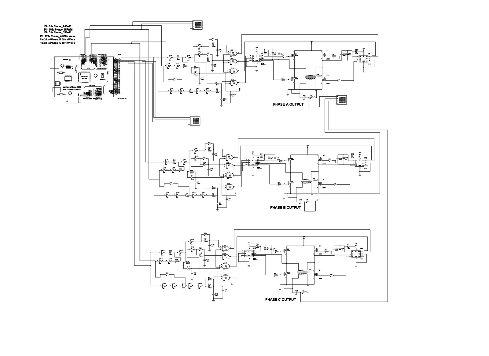
3 Phase Inverter Circuit Using Mosfet
Few days ago gohz made a 24v 2000w power inverter in home sharing some design schematics and circuit diagrams.
3 phase inverter circuit using mosfet. The circuit below shows a 3 phase inverter inverter circuit stage using h bridge mosfets configuration which receives the phase shifted pwms from the above stage and converts them into corresponding high voltage ac outputs for operating the connected 3 phase load normally this would be a 3 phase motor. With ni multisim and ni labview software you can implement desktop simulation of your entire analog and digital system before prototyping. This tutorial shows you how to use the multisim and labview cosimulation feature to achieve closed loop simulation of transistor level power electronics as well. 3 phase inverter system with.
1200v rated igbt module of current ratings from 50a 200a. Supporting multiple vendors 7 reinforced isolated igbt gate drivers iso5852s with working voltage isolation of 15kvrms with minimum cmti of 50 kvms. This is the circuit diagram of 3000w power inverter 12v to 230v modified sinus capable to deliver about 3000w 230v ac output from 12v input. This is the inverter circuit for professional only.
Hi its my first time build an inverter neh thing is the circuit diagram of the pwm doesnt seem to make sense as it shows the ic with all sided pins while the one at the bottom and the one i bought is two sided and also it doesnt say as to the porality of the ic or where the lines to the mosfets come from. Could you please grant me. A power inverter or inverter is an electronic device or circuitry that changes direct current dc to alternating current ac. The input voltage output voltage and frequency and overall power handling depend on the design of the specific device or circuitry.
This is inverter circuit 500w 12vdc to 220v 50hz. It easy to make and low cost. Using basic parts transistors 2n3055 ic 4047.


