Sg3525 Inverter Circuit Diagram
The circuit is based on lm317 positive and lm337 negative voltage regulators.
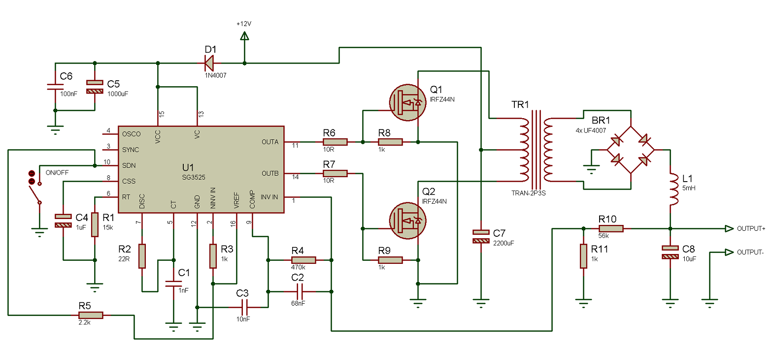
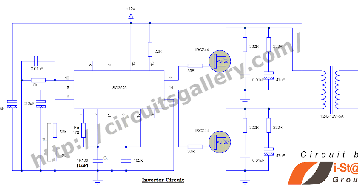
Sg3525 inverter circuit diagram. This sg3525 inverter circuit is suitable for 100 watt applications. This article contains circuit diagram ic features working and video demonstration of the circuit. Sg3525 is used extensively in dc dc converters dc ac inverters home ups systems solar inverters power supplies battery chargers and numerous other applications. Not being an expert on the use of the sg3524 i would do the following.
Disconnect the jfet gates fron the circuit and measure the pull up voltage at pins 1114. Simple low power inverter circuit 12v dc to 230v or 110v ac diagram using cd4047 and irfz44 power mosfet gallery of electronic circuits and projects providing lot of diy circuit diagrams robotics microcontroller projects electronic development tools. Few days ago gohz made a 24v 2000w power inverter in home sharing some design schematics and circuit diagrams. The picture was taken in short circuited.
Using two switch topology. When developing a welding inverter i applied forward inverter with two switches topology. Here the input line voltage traverses through the emi filter further smoothing with big capacity. In many situations we need to use mosfets configured as high side switches.
Many a times we need to use mosfets configured as high side and low side switches. This project is a solution to power up most of devices or projects requiring dual adjustable power supply.


